|
 |
|
This is only a sample
mount for the LED. This is not necessary. I just wanted to. I
figure I may be moving this system to another heli in
the future. So to make things easier put the work
in now. |
|
| |
|
|
 |
|
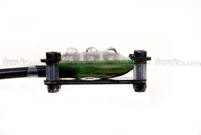
Carbon fiber material
was cut
to the size of the LED. Use fuel tubing and rubber
washers. An L-bracket is used for mounting. |
|
| |
|
|
 |
|
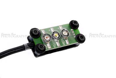
Mounted the LED
underneath the adapter plate.
Notice the
double-sided tape underneath the plate. This is to
prevent movement. Small strips is all that is
required. |
|
| |
|
|
 |
|
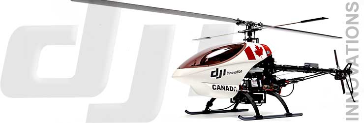
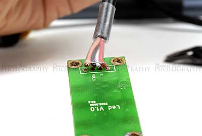
During the review the
wire
must have bent back and forth to cause the
soldering point to break.. |
|
| |
|
|
 |
|
Unsoldered the
wires. Re-strip, cleaned and re-soldered. New heat
shrinks were also used. |
|
| |
|
|
 |
|
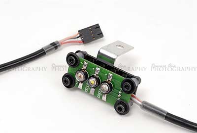
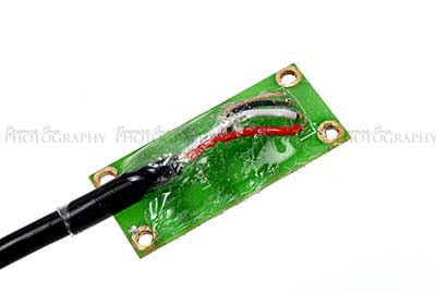
To prevent this from
happening again "Shoe Goo®" was used to protect the wires. |
|
| |
|
|
 |
|
Then used a clear
heat shrink to further protect the wires. The heat
shrink also protects the soldering points from shorting
them accidentally. |
|
| |
|
|
 |
|
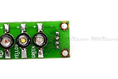
Cut holes for the LED
and reassembled with the carbon fiber plate.. |
|
| |
|
|
 |
|
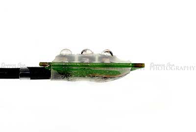
This assembly is much
more solid. |
|
| |
|
|
 |
|
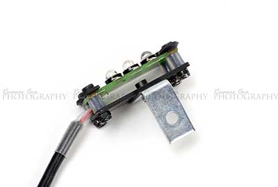
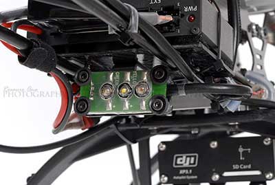
Mounted the LED in
the same place as previous. |
|
| |
|
|
 |
|
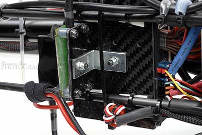
A closer look at the
L-bracket mounting. |
|
| |
|
|
 |
|
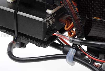
Plug the LED wire
into the LED port on the adapter.
Notice wire
protection on the LED wire. |
|
| |
|
|
 |
|
| |
|
| |
|
| |
|
|
UPDATE
- LED Replacement - May 14, 2009 |
|
| |
|
|
 |
|
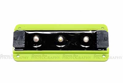
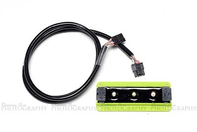
As promised, DJI sent
me a replacement LED.
No more exposed
solder connections. The LEDs are now sealed.
Its dimensions are
80mm x 34mm. |
|
| |
|
 |
|
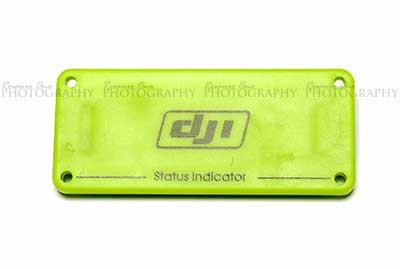
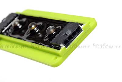
Solid back.
Safe to use Velcro or double-sided tape. |
|
| |
|
 |
|
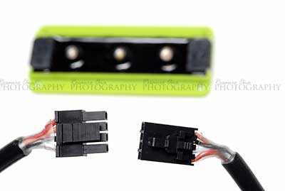
Cable can now be
separated. |
|
| |
|
 |
|
Either end of the LED
can be used to plug the cable into. |
|
| |
|
 |
|
Cable has two
different connectors. The connector to the left
plugs into the LED. |
|
| |
|
 |
|
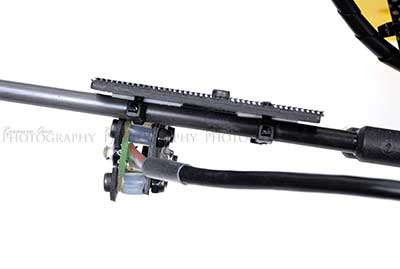
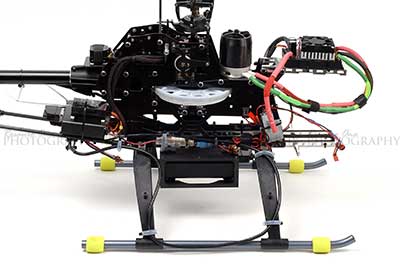
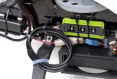
Mounted the LED on
the side using Velcro and tie-wraps. |
|
| |
|