|
|
|
|
 |
|
|
|
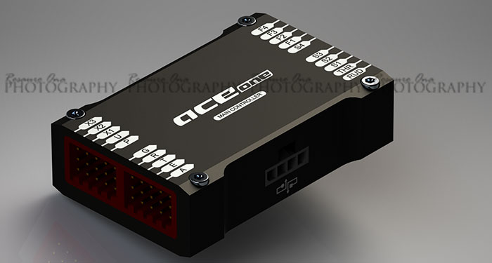
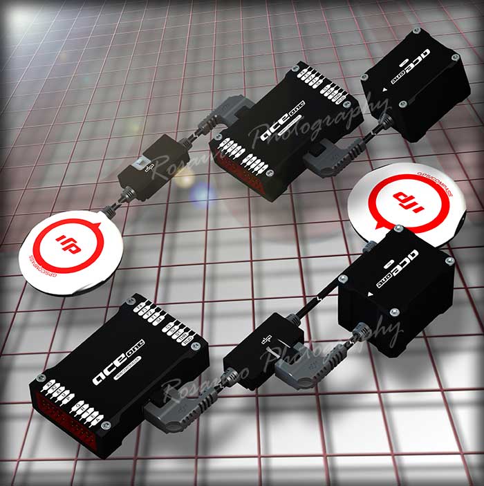
The main controller
is the heart of ACE ONE. This is where all the
components are connected to and where communication
between components takes place.
|
|
|
Before going any
further it's best to understand where everything plugs
into. |
| |
|
|
 |
| |
|
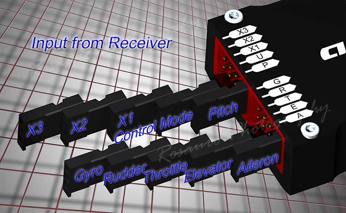
These
are inputs from your receiver. Use
the servo extensions provided.
|
A |
Aileron
channel |
|
E |
Elevator
channel |
|
T |
Throttle
channel |
|
R |
Rudder
channel |
|
G |
Gyro channel |
|
P |
Pitch channel |
|
U |
The control
mode. On a spare channel
used for switching between
flight modes.
It's best to
use a three position switch.
|
|
X1 |
This has
multiple functions. On a
spare channel
1 - Used to
control the tilt on your camera
gimbal
2 - Used to
remotely adjust gains. |
|
X2 |
On a spare
channel used to remotely adjust
gains.
|
|
X3 |
On a spare
channel used for engine speed
sensor.
|
|
|
|
| |
|
 |
| |
|
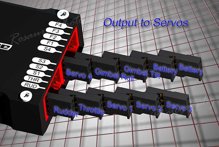
This
side of the main controller are the
outputs to servos.
|
RUD |
Tail servo
- Remember to use a step-down if
your tail servo is rated for
4.8v. |
|
THR |
ESC throttle
cable plugs in here. |
|
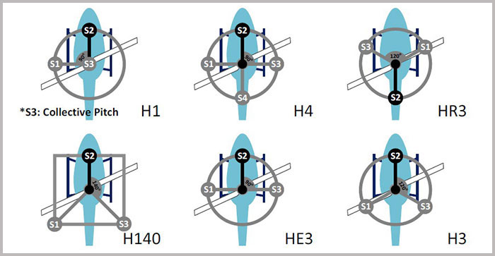
S1, S2, S3, S4 |
These are for
cyclic servos.
Remember to
first set your transmitter to
single-servo CCPM (H1 on Futaba,
1sNORM on JR/Spektrum and
1-Servo 90°
on Hitec)
Use the image
below to determine servo
allocation. |
|
F1 |
Gimbal roll
servo. |
|
F2 |
Gimbal tilt
servo. |
|
F3, F4 |
Battery
input.
NOTE:
Battery must be 4.8v to
8.4v.
Battery input
can be connected to any spare
input or output port on the main
controller. |
|
IMPORTANT: ACE ONE
components, servos and receiver
all use the same power source.
Use a large capacity battery.
A 4000mAh or higher is
recommended.
|
|
From the
manual
|
|
| |
|
|
 |
| |
|
|
The IMU can be
plugged directly into the Main Controller or into the
in-line CAN-Bus port of the GPS cable. |
|
| |
|
|
| |
|
|
Now that you have an
understanding of where everything goes here's how I
hooked mine up. |
| |
|
|
 |
|
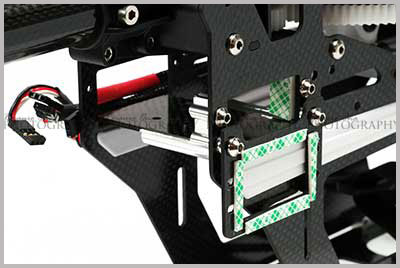
Find a location to
mount the main controller. |
|
| |
|
|
 |
|
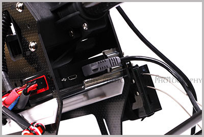
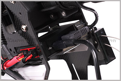
Remember to make sure
the USB port on the main controller is accessible. |
|
| |
|
 |
|
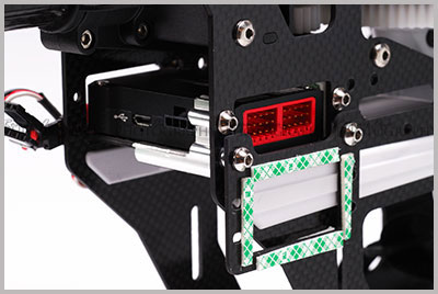
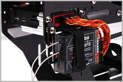
Plug the servo
extensions into the channels you will be using. |
|
| |
|
|
 |
|
Plug the servo
extensions into the input side of the main controller. |
|
| |
|
|
 |
|
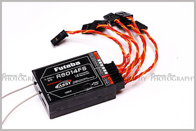
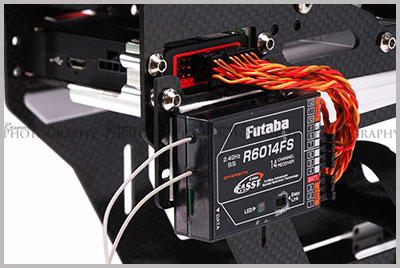
Back up the
receiver with Velcro. |
|
| |
|
|
 |
|
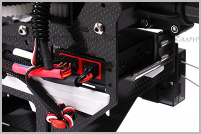
Plug the servos,
throttle (ESC) and power cables into the output side of
the main controller. |
|
| |
|
 |
|
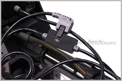
I used the in-line
CAN-Bus port of the GPS cable. |
|
| |
|
 |
|
Plugged in the GPS
cable into the Main Controller. |
|
| |
|
 |
|
Plugged in the
supplied USB
cable.
Clean up the cables
after you've set up everything in the software.
Ready for software
set up!
|
|
| |
|
|
|
|